Wiring Pumps Through a Bus Bar, Circuit Breaker and Pump Controller: A Step-by-Step Guide

Wiring pumps through a bus bar, circuit breaker, and pump controller is one of those tasks that separates a clean, reliable mobile rig from the kind that strands you on a job site tracing a short. Whether you're building a water fed pure water skid, a soft wash system, or a solar cleaning rig, the electrical backbone follows the same pattern — and getting it right the first time saves callbacks, burned components, and lost revenue.
What You Need
- ProTool Power Distribution Bus Bar (Red/Black pair)
- ProTool 40-Amp 12V Circuit Breaker — one per pump
- Spring V16 HC Pump Controller (35 amp, 12V) — one per pump
- 4–6 AWG wire for the trunk run (battery to bus bar)
- 12 AWG wire for branch runs (bus bar → breaker → controller)
- Appropriate ring terminals, butt connectors, and heat shrink
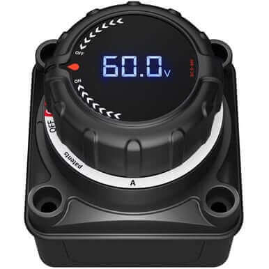
- A battery disconnect switch is strongly recommended at the battery
Step 1 — Trunk Wiring: Battery to Bus Bar
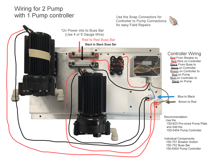
Run 4–6 AWG red wire from the positive terminal of your 12V battery (or battery bank) to the red bus bar. Run the same gauge black wire from the negative terminal to the black bus bar. Use ring terminals crimped and heat-shrunk at every connection. This trunk carries the combined current of every pump on the system, so undersizing it is the single most common wiring mistake on DIY skids — and the one most likely to melt something.
If you're pulling more than about 60 amps total (two 5 gpm pumps under load), step up to 4 AWG. For a single-pump cart, 6 AWG is adequate.
Step 2 — Branch Wiring: Bus Bar to Circuit Breaker to Controller
From the red bus bar, run a 12 AWG red wire to the input side of a 40-amp breaker. From the breaker's output side, continue with 12 AWG red to the red (positive) input on the pump controller. From the black bus bar, run 12 AWG black directly to the controller's black (negative) input.
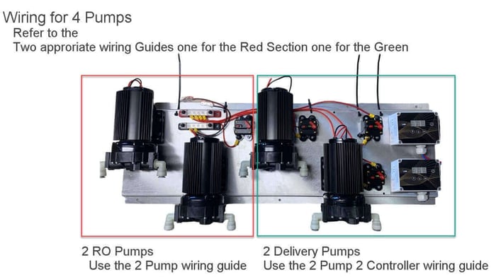
Repeat this pattern for each pump — each one gets its own breaker and its own controller. The bus bar is the central distribution point; the breakers isolate each branch so a fault on one pump doesn't take down the whole system.
Step 3 — Controller to Pump
The V16 HC controller outputs two wires to the pump:
- Brown wire from the controller → red wire on the pump (positive)
- Blue wire from the controller → black wire on the pump (negative)
The color crossover trips people up. Brown-to-red, blue-to-black. Label your connections or use colored heat shrink if you're running multiple pumps in a tight enclosure.
Why Circuit Breakers Instead of Fuses
Fuses work once. A breaker trips, you reset it, and you're back running. On a mobile rig where vibration can cause intermittent shorts, a breaker that trips and resets beats digging through a toolbox for a replacement fuse while the customer watches. Breakers also let you manually kill individual pumps for maintenance — pull the breaker arm and you've isolated that branch without touching the battery disconnect.
Why a Pump Controller Matters
Running a 12V diaphragm pump straight off the battery is electrically simple and operationally wasteful. A controller like the Spring V16 HC (rated to 35 amps) does three things that pay for themselves quickly:
- Speed regulation — match pump output to actual demand instead of running wide open. Less wasted water, less noise, lower battery drain.
- Soft start — reduces the inrush current spike that hammers diaphragm check valves and shortens pump life.
- Remote capability — the V16 HC WFP Link version adds long-range wireless on/off from the pole, so you're not walking back to the truck between windows.
The standard V16 (15 amp) handles single-pump residential setups. Move to the HC version when you're driving a 5 gpm delivery pump or a soft wash pump that draws more current under load.
Connection Summary
Red (Positive) Path
- 12V battery (+) → 4–6 AWG red → red bus bar
- Red bus bar → 12 AWG red → breaker input
- Breaker output → 12 AWG red → controller red input
Black (Negative) Path
- 12V battery (−) → 4–6 AWG black → black bus bar
- Black bus bar → 12 AWG black → controller black input
Controller to Pump
- Controller brown → pump red
- Controller blue → pump black
Common Mistakes
- Undersized trunk wire. Two pumps at 30 amps each on 12 AWG trunk wire will overheat. Size the trunk for total system draw, not per-pump draw.
- No breaker per pump. Sharing a breaker across two pumps means you can't isolate one for service without killing both.
- Skipping the bus bar. Twisting multiple wires onto a single battery terminal creates a rats-nest that corrodes, loosens, and eventually arcs. The bus bar exists to solve this.
- Reversed controller-to-pump colors. Brown goes to red, blue goes to black. Get it backwards and the pump runs in reverse (if it runs at all).
Recommended Components
All of these are stocked at J.Racenstein and spec'd for 12V mobile cleaning rigs:
- ProTool Power Distribution Bus Bar — red/black pair, rated for multi-pump systems
- ProTool 40-Amp Breaker Switch
- Spring V16 HC Pump Controller (35A, long-range remote)
- Spring V16 Pump Controller (15A) — for single-pump residential carts
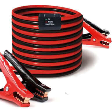
- ProTool 12V Power Cables for Pumps
- Battery Disconnect Switch with Meter
- ProTool 90 PSI 5.0 GPM Regulated Pump
Products Mentioned
 ProTool Power Distribution Buss (2) Red-Black12v SKU: 150-752 | 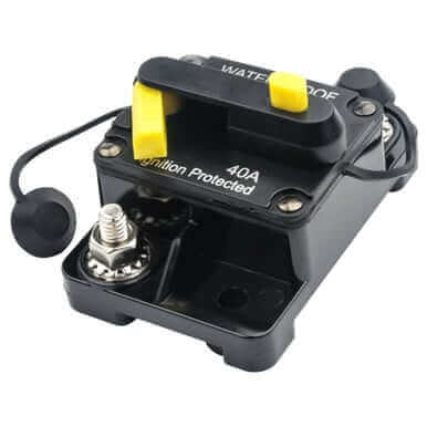 ProTool Breaker Switch 40amp 12v SKU: 150-751 | 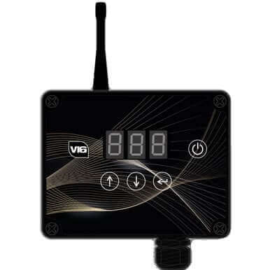 Pump Controller V16 HC WFP Link Long Range Remote Control 35amp 12v SKU: 150-5453 |
 Disconnect Switch with Meter SKU: 150-7512 | ProTool Breaker Switch 40amp 12v SKU: 150-751 | Pump Controller V16 HC WFP Link Long Range Remote Control 35amp 12v SKU: 150-5453 |
Pump Controller V16 HC WFP Link Long Range Remote Control 35amp 12v SKU: 150-5453 | 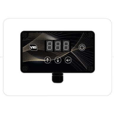 Pump Controller V16 15 Amp 12v SKU: 150-5440 | ProTool Power Distribution Buss (2) Red-Black12v SKU: 150-752 |
ProTool Breaker Switch 40amp 12v SKU: 150-751 | Pump Controller V16 HC WFP Link Long Range Remote Control 35amp 12v SKU: 150-5453 | Pump Controller V16 15 Amp 12v SKU: 150-5440 |
 Power Cables 12V for pumps SKU: 150-753 | Disconnect Switch with Meter SKU: 150-7512 | 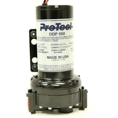 ProTool Pump 90psi 5.0gpm Pump Regulated SKU: 150-0856 |